| Print a Postscript Version of Lab Notes |
|


| Print a Postscript Version of Lab Notes |
|

|
INTRODUCTION:
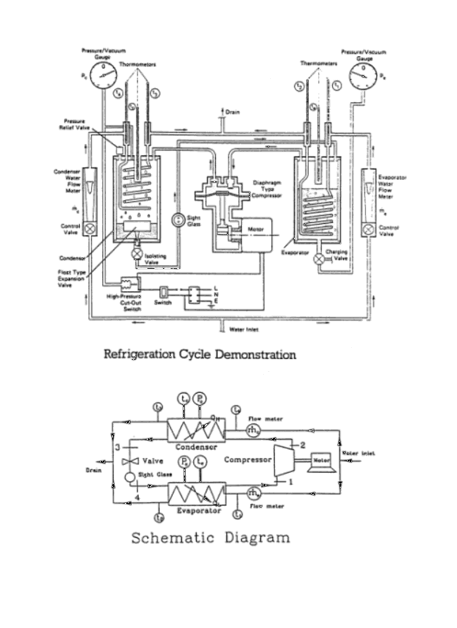
The attached figure shows schematically the basic refrigeration unit located in the Heat Transfer Lab, E3-2108. The working substance is R11, trichlorofloromethane. Carefully inspect the unit schematic and the cycle diagram. Identify the four key components of the basic refrigerator/heat pump: compressor, evaporator, condenser, and the expansion valve. Note that the unit is equipped with 2 pressure gauges, 6 thermometers, and 2 flow meters. Note that the pressure dials show the gauge pressure (not the absolute pressure), and that the flow meter readings are taken using the top of the float. There is a voltmeter and an ammeter for determining the power input to the electric motor driving the compressor. Note that this crude diaphragm-type compressor has only a 55% efficiency, and the heat loss from the compressor to the surrounding air is estimated to be 18 W under typical operating conditions. OPERATION: Turn on the water supplies (arbitrary amounts) to the evaporator and condenser, then switch on the compressor and allow the cycle to stabilize. DO NOT RUN THE UNIT WITH ZERO WATER FLOW. Carefully observe the following processes in the cycle:
THE TASK: Using the attached table of "OBSERVATIONS", record the room temperature and pressure, and all instrument readings after the unit stabilizes at arbitrarily chosen water flow rates between 5 gm/s and the maximum available amount.
|
|


| OBSERVATIONS: |
| Room Temperature (Ta) = | ________________ | oC |
| Barometer (mbar) = | ________________ | kN m -2 |
| Electrical power to run | ||
| the compressor motor: | ||
| Voltage = | ________________ | V |
| Current = | ________________ | A |
| Test No. | 1 |
| Evaporator Gauge Pressure, Pe (kNm-2) |  |
| Evaporator Temperature, Te (oC) |  |
| Evaporator Water Flow Rate, me (gm s-1) |  |
| Evaporator Water Inlet Temp., T1 (oC) |  |
| Evaporator Water Outlet Temp., T2 (oC) |  |
| Condenser Gauge Pressure, Pc (kN m-2) |  |
| Condenser Temperature, Tc (oC) |  |
| Condenser Water Flow Rate, mc (gm s-1 ) |  |
| Condenser Water Inlet Temp., T4 (oC) |  |
| Condenser Water Outlet Temp., T3 (oC) |  |
