The Microelectronics Heat Transfer Laboratory has experimental facilities and extensive experience in a wide variety of convection and thermal contact resistance measurements.
Natural and Forced Convection
Thermal Conductivity
Thermal Contact Resistance
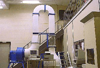
This unique, multi-purpose wind tunnel is designed for mixed and forced convection testing for horizontal, vertical and inclined geometries. By rotating the test section and duct assemble about a pivot axis coincident with the center line of the blower, the test section can be set to any angle between vertical and horizontal. The contraction section in the inlet plenum has a 9:1 contraction ratio and a 10 cm (4 in.) thick honeycomb flow straightener that reduces non-uniformities in the mean flow field and produces a relatively uniform velocity profile at the entrance of the test section. The removable, 30 cm x 30 cm x 60 cm (12 in. x 12 in. x 24 in.) test section is generally large enough to accomodate most common test specimens. Airflow velocities of 0 - 15 m/s (0 - 50 fpm) are controlled using a Danfoss VLT frequency-based speed regulator.
|
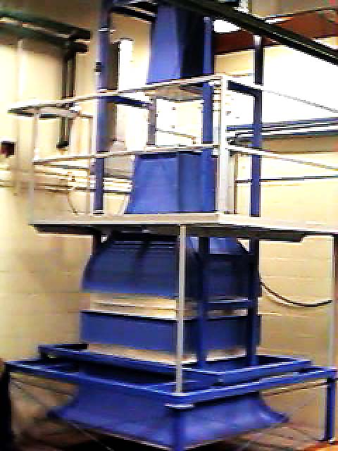
A recent addition to laboratory equipment at the MHTL, this vertical wind tunnel has a large 45 cm x 45 cm x 60 cm (18 in. x 18 in. x 24 in.) test section and is capable of airflow velocities from 3 m/s (10 fps) to 20 m/s (66 fps). The contraction has a 6.25:1 area ratio, with a symmetric cross section and analytical developed contours. The primary diffuser section expands with a total included angle of 6 degrees. The inlet section includes an aluminum honeycomb section and graduated mesh, high porosity screens and velocity variation in the test section is less than 1% variation from the mean, free stream velocity. Airflow velocity is controlled by a transistor invertor type variable frequency controller and velocity measurements are made using an anemometer.
|
The MHTL Natural Convection Test Enclosure is a vertical flowthrough apparatus designed specifically for use in natural convection experiments, where air flow is due soley to buoyancy effects. Ambient and heated air freely enters and exits the enclosure through inlet and outlet plenums, while the test section is protected from unwanted ambient air movements by honeycomb sections at the inlet and outlet. The vertically-oriented 45 cm x 30 cm x 45 cm test section is sufficiently large to hold full-size circuits boards and systems of boards for natural convection measurements.
|
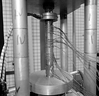
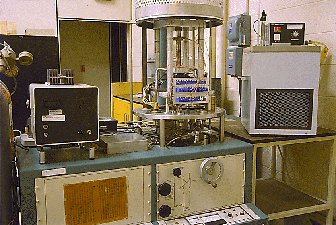
Thermal conductivity measurements are performed in the thermal contact resistance rig, a test apparatus enclosed in a Pyrex bell jar connected to a vacuum system which combines a mechanical pump connected in series with an oil diffusion pump. Using this system, a vacuum lower than 1E-07 torr is attained under ideal conditions, which stops any heat transfer from the test apparatus due to convection. The test column used for thermal conductivity measurements consists of two ARMCO iron heat meters placed in contact with the upper and lower surface of the test specimen.
|
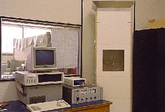
Two experimental rigs are available at the MHTL for measuring the thermal resistance between contacting surfaces. Available test conditions include contact pressures from 0.4 to 9.0 MPa, interface temperatures between 50 C and 250 C, and evacuated, helium or argon environments. Data acquisition and control over the experiment are performed using either an ACRO or a Fluke Helios data logger connected to an IBM PC compatible computer.
|
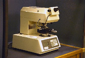
The Leitz Durimet Bench-Type Microhardness Tester is a manually-operated device with nine-present indenter loads between 15 and 2000 g. The test bed also allows heated specimens, up to 200 C, to be tested
|
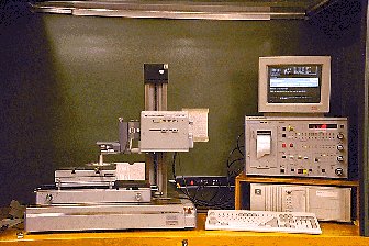
Talysurf 5 is a surface texture measurement device that determines surface roughness, waviness and profile for flat or circular surfaces. Test conditions can include a wide range of magnification settings, from 100X to 100,000X, and a range of traverse lengths from 0.56 mm to 56 mm. Cut-off lengths between 0.08 mm and 8 mm are available. A seperate analog-to-digital converter connected to the measuring device can recored digitized height readings at uniformly spaced intervals. This information is analyzed by the device to predict the CLA, the RMS roughness and the RMS surface slope for the surface being examined.
|
Overview | Course Info | Paper Library | Online Tools | Links