 |
 |
 |
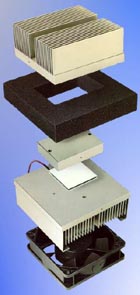
The heat sink geometry is specified using 6 geometric parameters,
including fin spacing and thickness, baseplate thickness, fin
height and length and the total number of fins.
|
|
Options are included for making the baseplate backing surface and
the end surfaces active or inactive.
|
|
Heat sinks can be modeled in an arrangement where identical
heat sinks are configured back-to-back, with symmetrical
heating.
|
|
The heat sink is subdivided into an inner and outer region,
where the inner region consists of a combination of
boundary layer and fully developed flow and the outer region
is composed of low Rayleigh flow conduction and boundary
layer flow.
|
|
The various models are combined using an approach introduced
by Churchill and Usagi for blending asymptotic solutions.
|